



Many electrical designers and contractors focus solely on matching cable tray size to current wiring demands during project design. This common shortcut leads to fully occupied tray systems right after commissioning, leaving no room for future upgrades, system adjustments or cable replacements. In industrial plants, data centers and commercial buildings, insufficient spare capacity is one of the top causes of post-construction rewiring, tray replacement and failed safety audits.
Planning spare capacity in a cable tray system is not a random reservation of empty space. It is a standardized engineering process that combines fill ratio standards, heat dissipation rules, future expansion prediction and maintenance accessibility. Proper capacity planning helps projects meet NEC and IEC compliance, extend system service life and avoid costly secondary renovations. As a professional cable tray manufacturer serving global engineering projects, BDCABLETRAY shares a practical, field-tested step-by-step guide for cable tray spare capacity planning in this article.
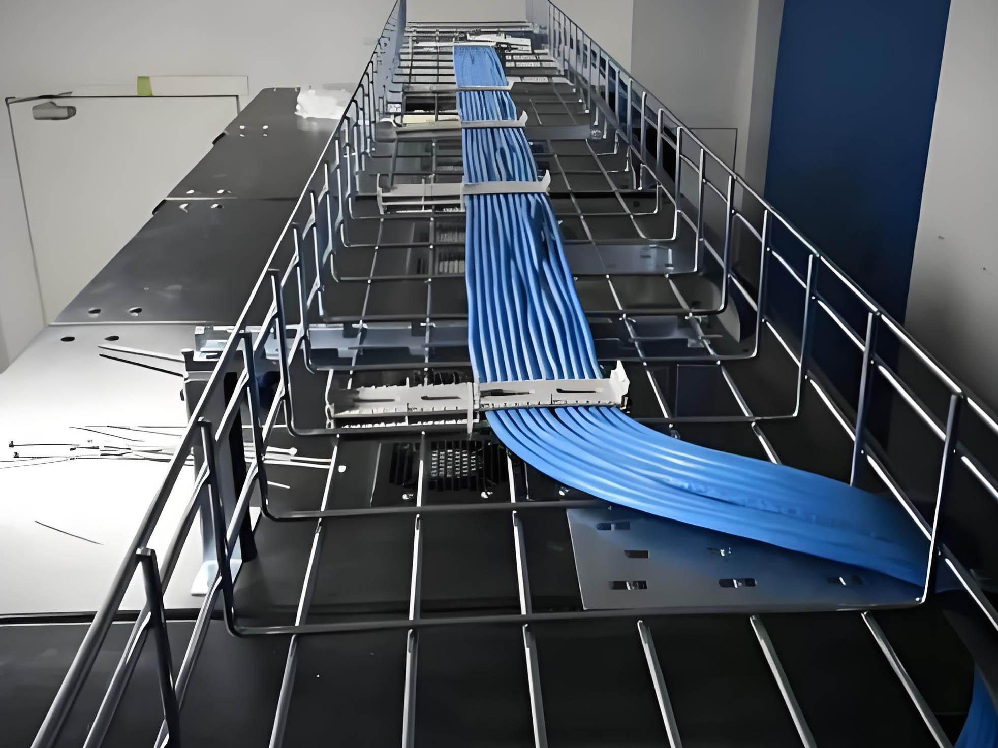
Understand Core Standards: Cable Tray Fill Ratio & Spare Margin Rules
Before designing spare capacity, engineers must clarify industry-standard fill ratios, as different cable types and tray structures have distinct spare space requirements. Blindly reserving space either causes material waste or fails to meet actual operational needs.
Standard Fill Ratio for Different Cable Types
Industry authoritative specifications divide fill rates according to cable application scenarios. Single-layer power cables allow a maximum fill rate of 50%, requiring 50% spare capacity. Multi-layer power cables and control cables adopt a 40% fill rate with 60% reserved space. For data cables, optical fibers and instrument cables, the recommended fill rate is 40% to 50% to ensure stable signal transmission and heat dissipation.
Recommended Spare Capacity Margin by Scenario
For conventional fixed buildings and stable production lines, a 25% to 30% spare capacity margin is sufficient. For fast-updating intelligent factories, data centers and expanding industrial parks, engineers suggest reserving 30% to 40% spare space. For long-term reserved corridors and special expansion zones, a 50% spare margin can effectively avoid later overall reconstruction.
Difference Between Structural Spare and Functional Spare
Structural spare refers to the empty space reserved for cable laying, while functional spare focuses on maintenance gaps and heat dissipation channels. Qualified capacity planning must take both into account. Only reserving laying space without considering heat gaps will still lead to cable overheating and aging risks.
Step 1: Calculate Exact Current Cable Cross-Sectional Area
Accurate data calculation is the foundation of scientific spare capacity planning. Many design errors stem from estimating cable quantity instead of precise area calculation, resulting in unreasonable reserved space.
Count All On-Site Cable Types & Specifications
Sort out all cables to be laid in the tray, including main power cables, branch control lines, communication cables and backup spare wires. Record the outer diameter and cross-sectional area of each cable specification to avoid missing weak-current lines and temporary backup cables.
Sum Up Total Occupied Area
Calculate the total occupied area of all cables according to single cable cross-section and laying quantity. Avoid overlapping calculation and compression estimation. Ensure the data reflects the real space occupied by on-site cable laying, providing accurate basic data for subsequent spare capacity reservation.
Step 2: Match Spare Margin According to Project Operation Attributes
Different project operation cycles and upgrade frequencies require differentiated spare capacity strategies. Unified margin reservation cannot adapt to complex engineering scenarios.
Stable Operation Scenarios (Office & Residential Buildings)
These projects have fixed electrical systems and low upgrade frequency. On the premise of meeting standard fill rates, reserve 20% to 25% spare capacity. It balances engineering cost and later maintenance needs, avoiding excessive material waste while meeting daily cable replacement and minor adjustment demands.
Dynamic Upgrading Scenarios (Factory & Production Line)
Industrial production lines often add new equipment and adjust processes, with frequent circuit upgrades. It is necessary to reserve 30% to 40% spare capacity to adapt to equipment iteration and process transformation, eliminating the need for repeated tray renovation.
High-Precision Scenarios (Data Center & Clean Workshop)
Data centers and intelligent workshops have dense weak-current cables and strict heat dissipation requirements. A 40% to 50% spare margin is required to ensure unobstructed air convection, stable signal transmission and convenient large-scale system upgrading and cable iteration.
Step 3: Combine Tray Structure to Optimize Spare Space Layout
Different cable tray structures have different spare capacity utilization efficiency. Simply reserving area without combining structural characteristics will lead to invalid spare space and hidden safety hazards.
Ladder Cable Tray Spare Capacity Planning
Ladder trays feature open ventilation structure, suitable for high-current power cables. When planning spare capacity, focus on reserving longitudinal heat dissipation gaps. Avoid dense stacking of new and old cables. Reserve sufficient spacing between cable layers to ensure air circulation and prevent heat accumulation caused by subsequent cable addition.
Wire Mesh Cable Tray Spare Capacity Planning
Wire mesh trays are mostly used for weak-current wiring. The open mesh structure has good heat dissipation. Spare space should focus on lateral expansion margin to facilitate later cable sorting and increase, avoiding messy cable entanglement caused by insufficient reserved width.
Solid & Perforated Cable Tray Spare Capacity Planning
Closed and perforated trays have relatively poor ventilation. The spare margin should be appropriately increased on the basis of standard fill rate. Priority should be given to reserving upper ventilation gaps to prevent the overall temperature rise of the cable bundle after adding new cables.
Step 4: Reserve Maintenance & Heat Dissipation Redundancy
Qualified spare capacity planning not only reserves laying space for new cables, but also guarantees daily maintenance and safe operation redundancy, which is easily ignored in conventional design.
Reserve Manual Operation Space
The reserved spare space must allow maintenance personnel to extract, replace and inspect single cables freely. Excessively compact spare gaps will lead to inability to operate during later maintenance, even if there is residual space, resulting in invalid spare capacity.
Independent Heat Dissipation Spare Gap
Superimposed laying of new and old cables will reduce overall heat dissipation efficiency. An independent heat dissipation spare gap needs to be reserved in the initial design to ensure that the cable operating temperature remains within the safe range after capacity expansion, avoiding insulation aging and overload tripping.
Step 5: Verify Compliance & Avoid Overcapacity Waste
After completing spare capacity planning, final standard verification and cost optimization are required to balance safety compliance and engineering economy.
Meet NEC & IEC Fill Rate Compliance
Check whether the final cable laying rate and spare margin meet international electrical standards. Avoid insufficient spare capacity leading to audit failure, and ensure that all reserved spaces are standardized and effective.
Control Comprehensive Engineering Cost
Excessively high spare capacity will increase tray specification and project cost. On the premise of meeting safety and expansion needs, reasonably match tray models to avoid blind oversizing, realizing the optimal balance of safety, usability and economy.
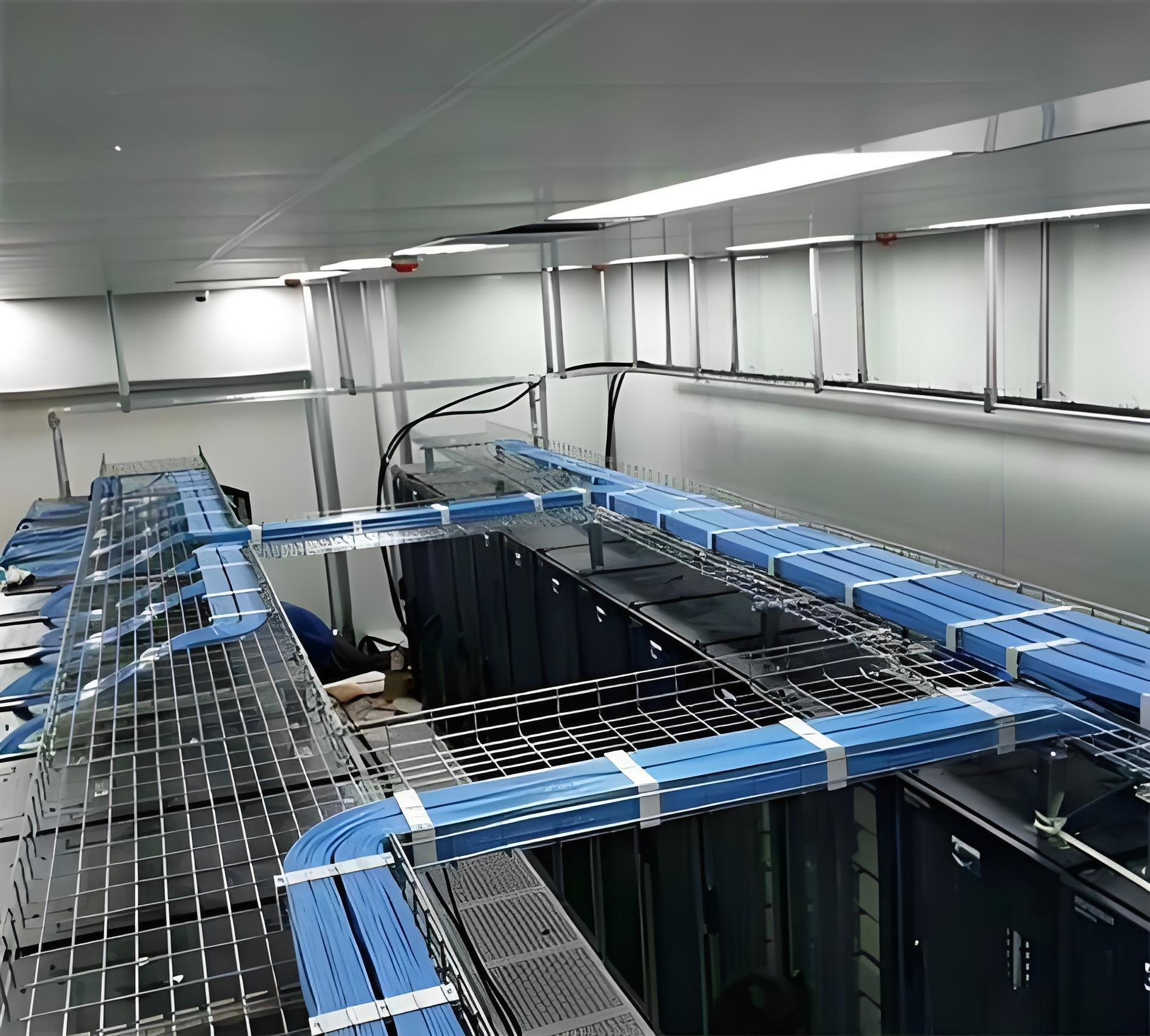
Common Mistakes in Spare Capacity Planning & Solutions
Only Consider Current Cable Quantity
Many designers calculate tray size purely based on initial cable quantity, resulting in full load at completion. Solution: Take the 3-5 year expansion demand of the project as the basis to superimpose spare margin, reserving effective space for long-term operation.
Unified Spare Margin for All Scenarios
Using a single 20% or 30% standard for all wiring zones leads to insufficient margin in key areas and waste in ordinary areas. Solution: Implement zoning differentiated planning according to functional attributes and upgrade frequency.
Ignore Structural & Heat Dissipation Restrictions
Only calculate area margin without considering structural gaps and heat dissipation requirements, resulting in valid data but invalid actual space. Solution: Combine tray structure and cable heat generation to conduct comprehensive capacity verification.
If you need professional cable tray spare capacity calculation, standardized layout planning and compliant product matching services for electrical engineering projects, contact BDCABLETRAY. Our senior engineering team provides free on-site scheme evaluation, fill rate verification and personalized tray selection solutions to help you complete safe, compliant and cost-effective spare capacity planning.
FAQ
1. What is the standard spare capacity for a cable tray system?
There is no fixed unified standard, and the margin is divided by scenario and cable type. Conventional building wiring requires 20%-25% spare capacity, industrial upgraded projects reserve 30%-40%, and data center weak-current wiring needs 40%-50% spare space. All planning must be based on the premise that the cable fill rate meets NEC and IEC specifications to ensure heat dissipation and safety redundancy.
2. Why can’t we fill the cable tray to full capacity from the start?
Full-capacity laying completely blocks air convection, causing cable heat accumulation and accelerated insulation aging. Meanwhile, it leaves no space for later equipment upgrades, cable replacement and daily maintenance. Once the system needs adjustment, only overall tray replacement or parallel laying can be adopted, resulting in huge renovation costs and project delays.
3. How to calculate effective spare capacity instead of theoretical margin?
Effective spare capacity needs to subtract heat dissipation gaps and maintenance operation space on the basis of theoretical area margin. It cannot be calculated simply by area proportion. It is necessary to combine cable outer diameter, laying layers and tray structure to simulate actual laying conditions, avoiding invalid spare space that cannot be used in actual operation.
4. Do different cable tray types require different spare margins?
Yes. Open ladder and wire mesh trays have good heat dissipation, and the spare margin can be moderately adjusted according to expansion demand. Closed solid trays have poor ventilation, requiring higher spare capacity to ensure heat dissipation. High-current power cable trays need more redundant space than ordinary signal cable trays to avoid overheating risks.
5. Can BDCABLETRAY provide professional spare capacity planning services?
Absolutely yes. BDCABLETRAY’s professional engineering team is familiar with international electrical standards and on-site construction practices. We can provide full-process services including cable quantity statistics, fill rate calculation, scenario-based spare capacity customization and tray model matching, ensuring your cable tray system is compliant, safe and upgradable for long-term operation.