


Last year we supplied cable tray for a 120 MW utility-scale solar plant in the Atacama region of Chile. The project was spread across 280 hectares of desert: over 300,000 PV modules in long rows, twelve inverter blocks, and a single 230 kV step-up substation at the center. The AC cabling from each inverter block to the substation had to run above ground for roughly 6.4 kilometers, crossing dry riverbeds, access roads and the occasional maintenance track.
The EPC contractor initially planned to bury the medium-voltage cables in trenches. Our engineering team pushed back after reviewing the route. Trenching 6.4 km in rocky desert soil, with a 2 m depth requirement and cable warning tape, was going to add weeks to the schedule and a lot of cost. We proposed an overhead ladder tray instead — elevated on steel posts, clear of the ground, easy to access for the 25-year life of the plant. This case walks through what we designed and how the install went.
Why Ladder Tray Won Over Buried Cable
Buried MV cable is the default for long outdoor runs, but in this site it was the slower and more expensive option. Ladder tray solved three specific problems the EPC was facing.
Long spans between supports
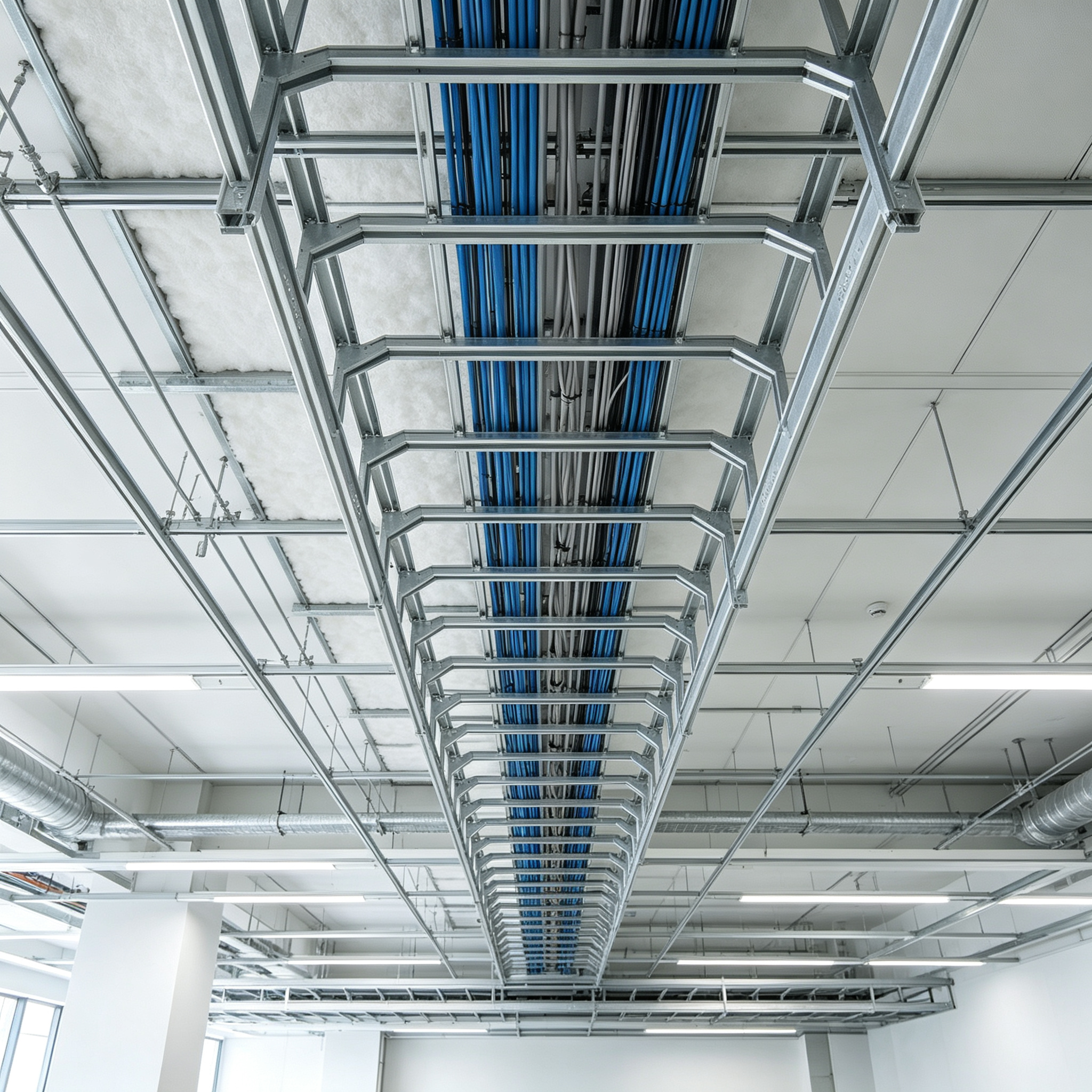
The desert site has no existing structures to hang cable from. We needed to carry heavy MV cables over long stretches between posts. Ladder tray is the strongest form factor per kilogram of steel: the side rails carry the load like a beam, and the rungs support the cable. We designed the system for a 3-meter support spacing, which cut the number of posts in half compared with wire mesh or solid bottom tray, both of which need support every 1.5 meters.
Heavy cable weight and heat dissipation
Each inverter block carried three 240 mm² MV power cables plus a fiber optic pilot cable. At full summer output the cables ran hot. Ladder tray is open on both sides, so air flows around the cable bundle and dissipates heat the way the cable rating tables assume. A solid bottom or covered tray would have forced the EPC to upsize the cables or derate the run — an expensive fix.
Desert UV, temperature swing and maintenance access
The Atacama sees UV levels among the highest on Earth, surface temperatures swing from near freezing at night to over 50°C during the day, and there is almost no rainfall. Powder coating would chalk and peel within a few years. We specified hot-dip galvanized steel, which handles UV and temperature cycling without a paint system. Elevating the cable also keeps it clear of the occasional flash-flood runoff that does happen in this desert — something the EPC had not considered when they planned burial.
Specs We Supplied
After three route reviews with the EPC’s electrical team and the local civil contractor, we locked the following BOM.
Main ladder runs
The main trunk from the inverter blocks to the substation used 600 mm wide ladder tray, 100 mm deep, side rails 3.0 mm thick, rungs at 300 mm spacing, hot-dip galvanized to ASTM A123. Total length on the main trunk was 4,800 meters. The smaller drops from each inverter block to the trunk used 300 mm × 100 mm ladder tray, another 1,600 meters, same material and coating.
Supports and posts
Because the route crossed open desert, we supplied 3-meter-high galvanized steel post supports every 3 meters along the route, with a crossarm on which the ladder tray sat. Posts were 100 × 50 × 3 mm C-channel, set in a pre-cast concrete footing poured by the local civil crew. At road crossings, we designed the tray to sit on a higher steel portal — 5.5 m clearance — so maintenance trucks and PV cleaning equipment could pass underneath without detouring.
Bends, reducers and earthing
We supplied prefabricated 90° horizontal and vertical bends, reducers from 600 mm to 300 mm, and expansion joints every 30 meters to handle the desert temperature swing. Because the tray runs outdoors in a lightning-prone region, we supplied bonded earthing jumpers across every splice, connected to the plant’s main earthing grid at each inverter block. The EPC’s electrical engineer signed off on the earthing design before production started.
Production, Documentation and Shipping
The EPC required batch-by-batch shipment, matched to the civil crew’s footing-pour schedule. We packed the order into eleven 40HQ containers over a four-month window.
Galvanizing and coating verification
All tray sections were hot-dip galvanized after fabrication. Before shipment, our QC measured zinc thickness on random samples — target was 85 microns minimum per ASTM A123. We also ran a visual check on every rung weld, because a weak weld on a rung under heavy cable load is a real failure point. The EPC’s own inspector visited the factory on two batches and signed off on the process.
Container loading by route section
Because the route was linear, we numbered the containers R1 through R11 to match the kilometer markers along the route. Each container held the tray, posts, bends and accessories for a 600-meter segment. When the trucks arrived on site, the civil crew unloaded straight to the correct post position instead of sorting in a staging yard. The EPC told us this cut their on-site material handling time by about 30%.
Installation and First Year Operation
The local civil crew poured footings and set posts. Our engineer joined the first 500 meters by video call, walking them through post alignment, ladder tray seating on the crossarms and the earthing jumper connections. The crew picked it up quickly and finished the rest of the route on their own.
The plant has now been in operation for over a year. We checked in with the EPC’s site supervisor during a recent maintenance visit. The tray shows no rust streaks, no coating failure at the rung welds, and no visible sag between supports despite summer cable loads. The expansion joints are doing their job — the EPC reports no distorted splices from the temperature cycle. The EPC has already contracted us for a second solar block on the same site, using the same 600 mm hot-dip ladder spec.
If you are specifying cable routing for a solar farm, wind farm, refinery, long industrial corridor or any outdoor run where long spans, heavy cable and corrosion resistance matter, contact BDCABLETRAY. Send us your route length, cable schedule, support spacing requirement and environmental conditions — we will come back with a tray spec, support layout and a batch-by-batch delivery plan within two working days.
FAQ
1. What is the typical maximum span for ladder cable tray?
With standard 3.0 mm side rails, ladder tray typically supports 1.5 m to 3 m between hangers, depending on cable load. Heavier rail gauges (3.5–4.0 mm) extend that to 4–5 m. We will design the rail thickness and rung spacing from your actual cable weight per meter — not from a generic catalog number.
2. Is hot-dip galvanized enough for outdoor desert or coastal use?
Hot-dip galvanizing to ASTM A123 handles UV, temperature cycling and dry outdoor exposure well for 20+ years. For coastal sites with salt spray, or wash-down environments, we recommend adding a powder coating or upgrading to aluminum or 316 stainless. Tell us your site conditions and we will recommend the right finish.
3. Can you supply the posts and footings, or just the tray?
We supply the tray, support brackets, crossarms and earthing jumpers. The concrete footings are usually poured by your local civil crew because they need local concrete and site access. We provide the footing drawing and anchor bolt pattern so your civil team can pour to match.
4. How do you handle thermal expansion on long outdoor runs?
We specify expansion joints every 25–30 meters on outdoor hot-dip runs, and flexible bonding jumpers across each joint. The exact spacing is calculated from the temperature range your site sees. We will include the joint count and jumper hardware in your BOM.
5. What is the lead time for a multi-kilometer ladder tray project?
Standard hot-dip ladder tray in common widths ships in batches of 1,000–1,500 meters every 2–3 weeks after drawing approval. For a 6 km project like the solar plant, total production runs 3–4 months, aligned to your civil schedule. We will work backward from your energization date.