



On any commercial, industrial, or data center wiring project, inaccurate cable tray dimension checks before installation are one of the top causes of on-site rework, material waste, and delayed project delivery. Many field teams rely solely on design drawings without verifying actual site conditions, tray physical parameters, and matching tolerance. Small errors in width, height, thickness or length can lead to unfit installation, insufficient cable accommodation, poor load-bearing performance, and even project acceptance failure.
Accurate dimension inspection before installation is a necessary step to ensure smooth wiring construction and long-term stable operation of the cable management system. To help electrical contractors and site engineers standardize pre-installation inspection processes and avoid common construction mistakes, BDCABLETRAY shares a complete, field-tested cable tray dimension checking method covering core parameters, on-site verification steps and matching standards.
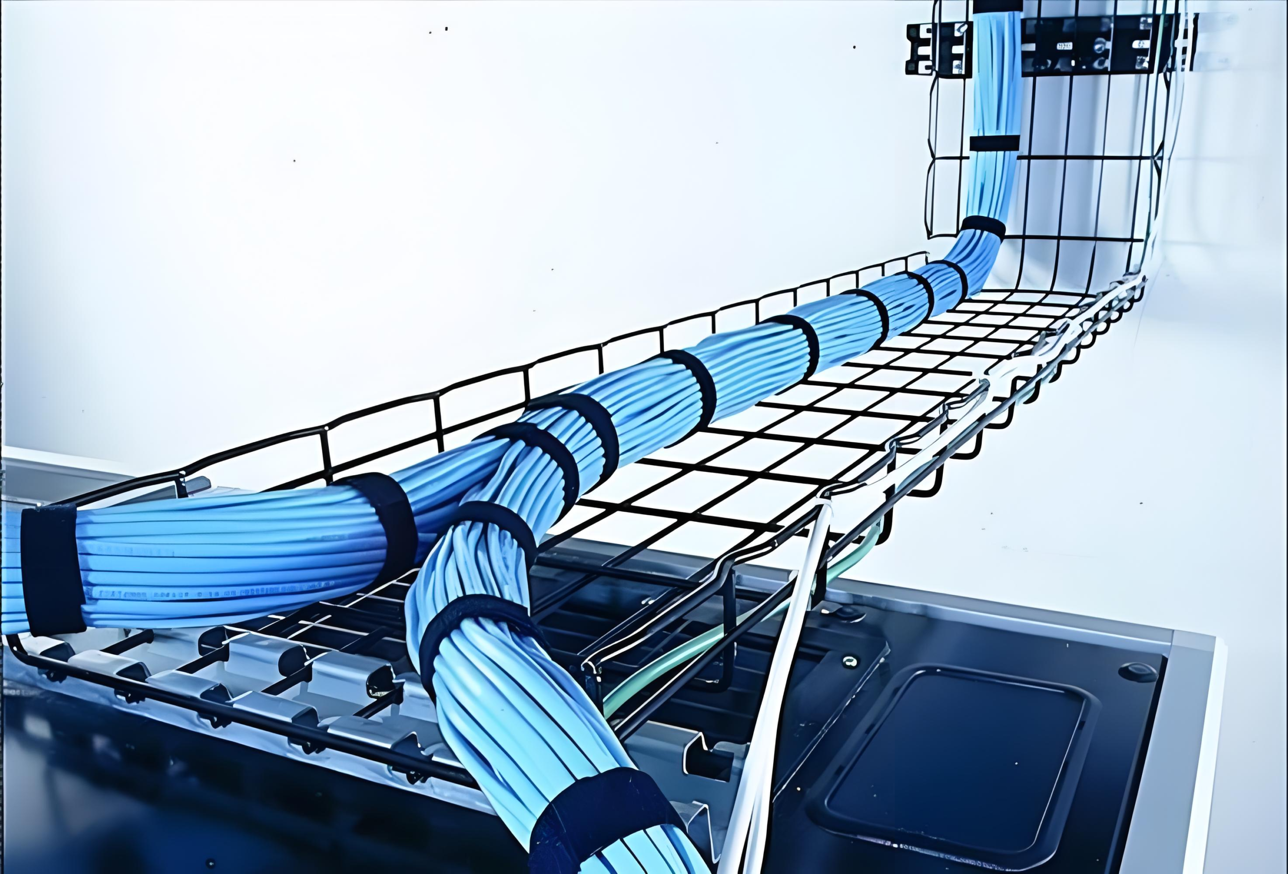
Why Pre-Installation Cable Tray Dimension Checks Are Indispensable
Design drawings provide theoretical data, but actual factory production errors, on-site building structure deviations and construction reserved space differences will lead to dimensional mismatches. Skipping pre-installation inspection often triggers a series of practical construction problems that affect project quality and progress.
Avoid on-site rework and material waste
If the tray width or height does not match the reserved ceiling space or cable laying volume, workers cannot carry out normal installation. Unchecked oversized or undersized trays can only be returned or modified on-site, resulting in wasted materials, increased labor costs and delayed construction schedules.
Ensure sufficient cable laying capacity
Blind installation without dimension verification may lead to insufficient internal tray space. After laying power cables, network lines and signal lines, the cables will be overcrowded, affecting heat dissipation, causing line extrusion and accelerating insulation aging, bringing hidden dangers to long-term electrical safety.
Guarantee overall structural stability and load performance
Tray plate thickness, side rail height and single-section length directly determine load-bearing capacity and supporting span. Substandard dimensional parameters will cause insufficient structural strength, leading to tray sagging, deformation or even collapse after cable laying, failing to meet industrial safety standards.
Meet project acceptance and compliance requirements
Formal engineering acceptance has strict standards for cable tray dimensional tolerance. Pre-installation full inspection can ensure all parameters meet design specifications and industry standards, effectively avoiding project acceptance failures caused by dimensional deviations.
Core Cable Tray Dimensions That Need Full Inspection Before Installation
Complete dimension checking is not limited to basic length and width. It needs to cover appearance size, structural thickness, accessory matching size and tolerance range. Each parameter is critical to the final installation effect and system stability.
Basic outer width and inner clear width
The outer width determines whether the tray can adapt to on-site reserved installation gaps and ceiling spaces, while the inner clear width is the key data to calculate cable laying capacity. It is necessary to use a professional tape to detect the actual width of each batch of trays, confirm that the dimensional tolerance is within the industry allowable range, and avoid inner space shortage caused by excessive outer frame thickness.
Side rail height and effective depth
Side height directly restricts the number of stacked cables and anti-falling performance. Too low side rails cannot fix cables stably, and high cables are prone to slipping off. During inspection, confirm the effective vertical depth of the tray, match the actual cable laying height required by the project, and ensure it meets the safety laying standard of no over-height stacking.
Plate thickness of bottom and side rails
Thickness is the core parameter affecting load-bearing and service life. Many low-quality trays have nominal thickness inconsistent with actual thickness. Before installation, use a caliper to measure the thickness of the bottom plate and side rails in multiple positions. Ensure the actual thickness conforms to the design standard, preventing structural deformation caused by insufficient thickness after loading cables.
Single section length and splicing tolerance
Check the actual length of each tray section to match the on-site laying span and hanger spacing. At the same time, detect the flatness of the splicing end face to ensure seamless docking between trays. Uneven length and unqualified end faces will lead to uneven overall laying and gaps after splicing, affecting the overall aesthetics and structural stability.
Special structural size for different tray types
Different types of cable trays have unique structural dimensions that need targeted inspection. For ladder trays, check rung spacing and rung width; for perforated trays, verify hole diameter and hole spacing; for wire mesh trays, confirm grid size and wire diameter. Special elbow, tee and reducing accessories need to check bending radius and transition size to ensure perfect matching with straight trays.
Standard Step-by-Step Dimension Checking Process On-Site
Standardized inspection procedures can avoid missed detection and misjudgment. BDCABLETRAY summarizes mature on-site operation steps for engineering teams to implement unified pre-installation dimension verification.
Step 1: Sort out design parameters and inspection standards
Before inspecting incoming trays, sort out the design drawing specifications, including tray model, standard size, allowable tolerance range and matching accessory parameters. Clarify the inspection benchmark to avoid judging product qualification based on experience alone.
Step 2: Random sampling and multi-point dimensional measurement
For batch incoming trays, adopt random sampling inspection. Measure the width, height, thickness and length of each sampled tray at multiple positions (both ends and middle position) to avoid detection errors caused by individual product bending and irregularity.
Step 3: Verify matching size with on-site installation environment
Compare the measured actual tray dimensions with on-site reserved ceiling height, aisle width and hanger installation spacing. Confirm that the tray can be installed smoothly without space conflict, and the supporting span matches the tray load standard.
Step 4: Inspect accessory and connection size compatibility
Check whether the size of connecting plates, bolts, hangers and special accessories matches the main tray. Ensure the fastener hole position and aperture are consistent, avoiding the problem that accessories cannot be installed or the connection is unstable due to dimensional mismatch.
Step 5: Record data and screen qualified products
Record all inspection data truthfully, screen out trays with unqualified dimensional tolerance, and mark them separately to prevent mixed installation of unqualified products. Form complete inspection records for project filing and later acceptance.
Common Dimensional Errors & Pre-Installation Avoidance Tips
Most on-site dimensional problems come from neglected details and non-standard inspection methods. Targeted prevention can effectively improve installation qualification rate and construction efficiency.
Ignoring thickness tolerance leads to insufficient load capacity
Many teams only check length and width but ignore plate thickness. It is recommended to focus on thickness detection for heavy-load power cable trays, and strictly reject products with insufficient thickness to avoid later deformation and safety hazards.
Uniform inspection standards not adopted for batch products
Batch production trays may have individual deviations. Unified sampling inspection standards must be implemented, and random inspection of individual products is not allowed to represent the overall batch quality, so as to avoid missing unqualified products.
Neglecting accessory matching dimensional deviation
Even if the main tray size is qualified, unqualified accessory size will also affect installation. Before construction, the full set of matching accessories must be inspected synchronously to ensure unified dimensional standards for the whole system.
If you lack standardized pre-installation dimension inspection standards, or need customized cable tray size matching and technical guidance for your wiring project, contact BDCABLETRAY. Our professional engineering team provides free size verification, on-site installation guidance and full-process technical support to ensure your project construction is error-free and acceptance-qualified.
FAQ
1. Why do cable tray dimensions differ between design drawings and actual products?
Factory production has reasonable industrial tolerance ranges, and individual product deviations may occur in batch production. In addition, different manufacturers have slight differences in frame design and plate making processes. This makes pre-installation physical dimension checking essential to eliminate mismatches between theoretical data and actual products.
2. What is the allowable dimensional tolerance for standard cable trays?
Conventional industrial cable trays have a width and length tolerance of ±2mm, and plate thickness tolerance strictly follows design and industry standards. Excessive deviation will affect installation matching and structural stability. BDCABLETRAY products strictly control tolerance within the national and international standard range to ensure on-site installation accuracy.
3. Can minor dimensional errors be used for on-site installation?
It depends on the error range and project requirements. Minor deviations within the allowable tolerance range will not affect use and installation. However, errors exceeding the standard tolerance must be returned or corrected in time. For high-standard data center and precision workshop projects, zero excessive deviation is required to ensure long-term stable operation.
4. How to quickly check cable tray dimensions in large-batch projects?
Adopt scientific stratified sampling inspection: select multiple groups of products from different batches and different packaging boxes for multi-point measurement. Focus on detecting core parameters such as thickness and inner width that affect use performance. Cooperate with unified data recording to realize efficient and accurate batch inspection.
5. Will unqualified tray dimensions affect project acceptance?
Yes. Cable tray dimensional compliance is a basic inspection item for electrical engineering acceptance. Unqualified size tolerance, insufficient thickness and mismatched structural size will directly lead to unqualified project inspection, requiring rework and rectification, which seriously affects project progress and engineering quality evaluation.