



When designing industrial and commercial cabling systems, electrical contractors and project engineers frequently face a common sizing dilemma: choosing the right cable tray width to match the exact number of cables on-site. Many small-scale projects either adopt oversized trays that cause budget waste or use undersized widths that lead to overstuffed, overheating cable layouts. The correlation between cable tray width and cable quantity is not random—it follows industry loading standards, heat dissipation rules and on-site laying specifications that directly determine cabling safety, service life and project compliance.
Improper width and quantity matching will lead to serious hidden risks, including poor air circulation, accelerated cable insulation aging, difficult later maintenance and even project acceptance failure. BDCABLETRAY, with years of industrial cable tray manufacturing and engineering customization experience, breaks down the practical relationship between tray width and cable quantity. This guide delivers field-tested sizing rules to help engineers make accurate, cost-effective and compliant layout decisions.
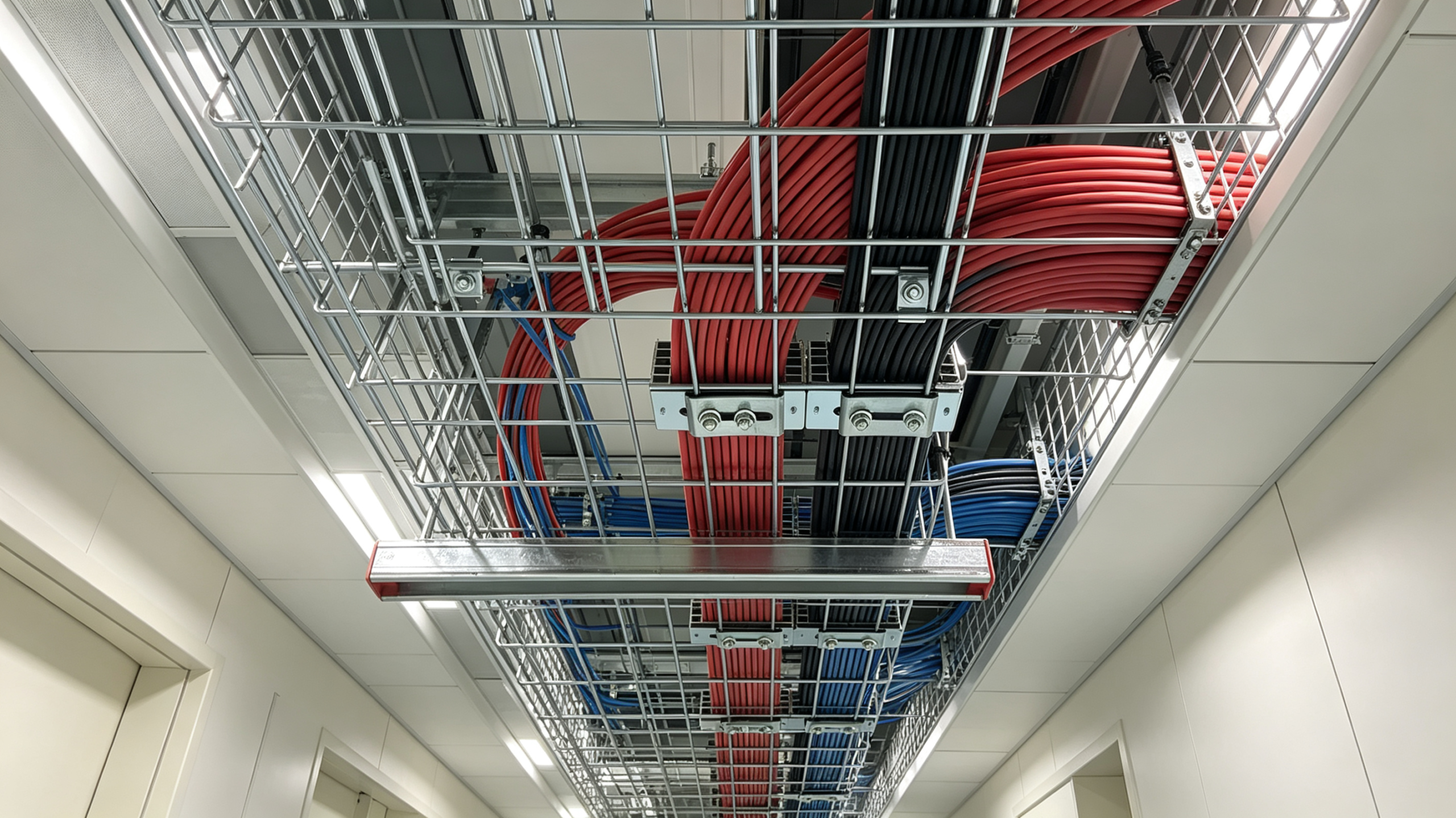
Basic Industry Standards for Cable Tray Loading Capacity
Before matching tray width and cable quantity, it is necessary to clarify the universal industry laying standard. Most international electrical codes stipulate that cables cannot fully occupy the inner space of the tray. Reserved gaps for heat dissipation, cable movement and later line expansion are mandatory for standardized cabling projects.
Standard cable filling ratio requirements
For conventional power cable trays, the safe filling ratio is controlled between 40% and 60% of the tray’s inner cross-sectional area. For weak current signal cables and communication lines with dense arrangement, the filling ratio should not exceed 50%. This reserved space ensures natural air convection, avoids heat accumulation caused by dense cable stacking, and leaves room for routine cable inspection and later wiring upgrades.
Why full cable laying is strictly prohibited
Fully filling the cable tray with wires completely blocks air flow. Long-term high-temperature operation of power cables will generate continuous heat, which cannot be dissipated in time. This will raise the internal temperature of the tray, accelerate insulation aging, increase circuit resistance, and greatly improve the probability of short circuit and leakage accidents. In addition, fully packed cables are prone to extrusion damage during vibration and displacement.
How Cable Tray Width Directly Determines Maximum Cable Quantity
Cable tray width is the core parameter that restricts the number of laying cables. Under the same plate height and laying environment, the wider the tray, the larger the transverse laying space, and the more cables can be arranged in a single layer. Different width specifications have clear applicable cable quantity ranges in actual engineering scenarios.
Narrow width trays for limited cable layouts
Small-size cable trays with widths of 100mm, 150mm and 200mm are suitable for single-type cable laying with small quantities. They are commonly used for local branch lines, equipment terminal connecting lines and single-row weak current wiring. Due to the narrow transverse space, these trays only support a small number of thin cables, and multi-layer stacking is not recommended to avoid heat accumulation.
Medium width trays for conventional engineering wiring
Trays with widths ranging from 300mm to 400mm are the most widely used specifications in industrial and commercial projects. They can accommodate mixed laying of power cables, control cables and signal cables. With reasonable single-layer arrangement, they can meet the daily wiring needs of most factory workshops, office buildings and supporting facilities, balancing space utilization and heat dissipation performance.
Wide width trays for large-scale dense cabling
Wide specifications of 500mm, 600mm and above are designed for central trunk wiring, factory main power lines and large-scale integrated cabling projects. They can bear dense multi-specification cable layout, meet the high-capacity wiring demand of core electrical systems, and ensure sufficient heat dissipation gaps even under full-load laying conditions.
Key Factors That Affect Width and Cable Quantity Matching
Tray width is not the only factor that determines the number of cables. In actual on-site matching, cable thickness, laying layers, usage environment and tray type will also change the final safe cable quantity, which cannot be calculated mechanically according to width alone.
Cable thickness and wire type difference
Thick high-voltage power cables occupy a large cross-sectional area, so the maximum laying quantity of the same width tray is small. In contrast, thin network cables, control lines and signal wires are densely arranged, with a larger quantity under the same width. Mixed laying of thick and thin cables requires more reserved gaps, which further reduces the actual loadable quantity.
Single-layer vs multi-layer laying rules
Single-layer flat laying is the safest wiring method with the best heat dissipation effect and the largest effective quantity matching range. Multi-layer stacking can increase the cable quantity in a single tray, but it will seriously block heat dissipation. For high-power and long-term operating circuits, multi-layer stacking is not recommended even if the tray width is sufficient.
Environmental temperature and heat dissipation requirements
For high-temperature workshops, closed ceiling wiring and poorly ventilated pipe corridors, the ambient heat dissipation condition is poor. Even with a standard-width tray, the actual laying cable quantity needs to be appropriately reduced to lower the operating temperature of the cable and avoid overheating aging.
Tray structural type differences
Fully enclosed solid bottom cable trays have relatively poor natural ventilation, so the safe cable quantity needs to be reduced by 10%–15% compared with open ladder trays of the same width. Open and perforated trays have better air convection performance, allowing a more reasonable cable quantity layout under the same width specification.
Common Matching Mistakes in Actual Engineering Projects
Most cabling safety hazards and acceptance problems stem from unreasonable matching of tray width and cable quantity. Summarizing typical mistakes can help engineering teams avoid repeated rectification and hidden safety risks.
Blindly choosing narrow trays to save costs
Many projects pursue low initial procurement costs and select narrow-width trays for large-quantity cabling. This leads to overcrowded cables, serious heat accumulation, and continuous temperature rise during peak power consumption. It not only shortens cable service life but also easily triggers circuit failure and affects stable operation of electrical equipment.
Excessively wide trays causing resource waste
Using oversized wide trays for a small number of cables will cause space waste and increase procurement and installation costs. Meanwhile, excessively loose cable layout is prone to irregular swinging and messy wiring during long-term operation, which is not conducive to standardized on-site management.
Ignoring future expansion during sizing
Many sizing schemes only calculate the current cable quantity, ignoring later equipment upgrading and circuit expansion. After the project is put into operation, there is no reserved space for new cables, forcing secondary transformation and re-laying, resulting in repeated investment and construction delays.
BDCABLETRAY Professional Width & Quantity Sizing Advantages
BDCABLETRAY focuses on engineering-oriented cable tray customization and sizing services. We do not adopt rigid standard matching but combine actual project conditions to provide accurate width selection schemes, ensuring safety, compliance and cost control.
Accurate engineering calculation standard
Our technical team calculates the most suitable tray width according to actual cable specifications, quantity, laying methods and environmental conditions, strictly following international filling ratio standards to avoid overloading or excessive redundancy.
Custom width specification support
In addition to conventional standard widths, BDCABLETRAY supports non-standard customized tray width production, which can perfectly match special wiring quantity requirements of personalized projects, solving the problem of insufficient or redundant space of standard trays.
Reserved expansion space design
We reserve reasonable wiring space according to the customer’s future factory upgrading plan, ensuring that the tray can meet the cable quantity demand of long-term operation and avoid secondary renovation costs.
If you are confused about cable tray width selection and cable quantity matching for your project, or need professional cabling sizing suggestions, contact BDCABLETRAY. Our engineering team provides free on-site scheme evaluation, accurate parameter matching and one-stop customized cable tray solutions to help you build safe, compliant and cost-effective industrial cabling systems.
FAQ
1. What is the core relationship between cable tray width and cable quantity?
Cable tray width directly determines the maximum safe laying quantity of cables. Under the same height and structural type, the wider the tray, the more cables it can hold. The two present a positive correlation, but the actual quantity must follow the 40%–60% safe filling ratio, instead of unlimited increase with width.
2. Can I increase cable quantity by stacking multiple layers in a narrow tray?
It is not recommended. Multi-layer stacking in narrow cable trays will seriously block air circulation, cause heat accumulation and accelerate cable insulation aging. Most standardized industrial projects prohibit dense multi-layer stacking, which will lead to safety audit failure and potential circuit risks.
3. Do different tray types affect cable quantity under the same width?
Yes. Under the same width specification, open ladder and perforated trays have better heat dissipation and can hold slightly more cables. Fully enclosed solid bottom trays have poor ventilation, so the safe cable laying quantity needs to be appropriately reduced to avoid overheating hazards.
4. What problems will mismatched tray width and cable quantity cause?
Undersized width with excessive cables will cause overheating, cable aging, short circuit risks and unqualified acceptance. Oversized width with too few cables will cause cost waste and messy loose wiring, increasing unnecessary procurement and construction costs.
5. How to choose the most cost-effective cable tray width for my project?
You need to calculate the total cross-sectional area of all on-site cables, reserve 40%–60% heat dissipation and expansion space, and select the matching tray width according to the tray type and laying environment. For complex mixed cabling projects, you can consult BDCABLETRAY engineers for free accurate sizing.