



For electrical contractors, project estimators and site engineers, cable tray takeoff is one of the most critical yet easily overlooked steps in industrial and commercial wiring projects. Many on-site material shortages, excess inventory waste and budget overruns stem from inaccurate cable tray material estimation. A rushed or rough takeoff often leads to delayed construction schedules, emergency supplementary orders and unnecessary project cost losses.
A precise cable tray material takeoff does not only calculate basic tray lengths. It covers tray types, supporting hardware, connecting accessories, special fittings and reasonable construction allowance. With rich on-site project experience, BDCABLETRAY shares a practical, step-by-step cable tray takeoff and material estimation guide, helping engineering teams complete accurate budgeting, avoid construction risks and improve project profitability.
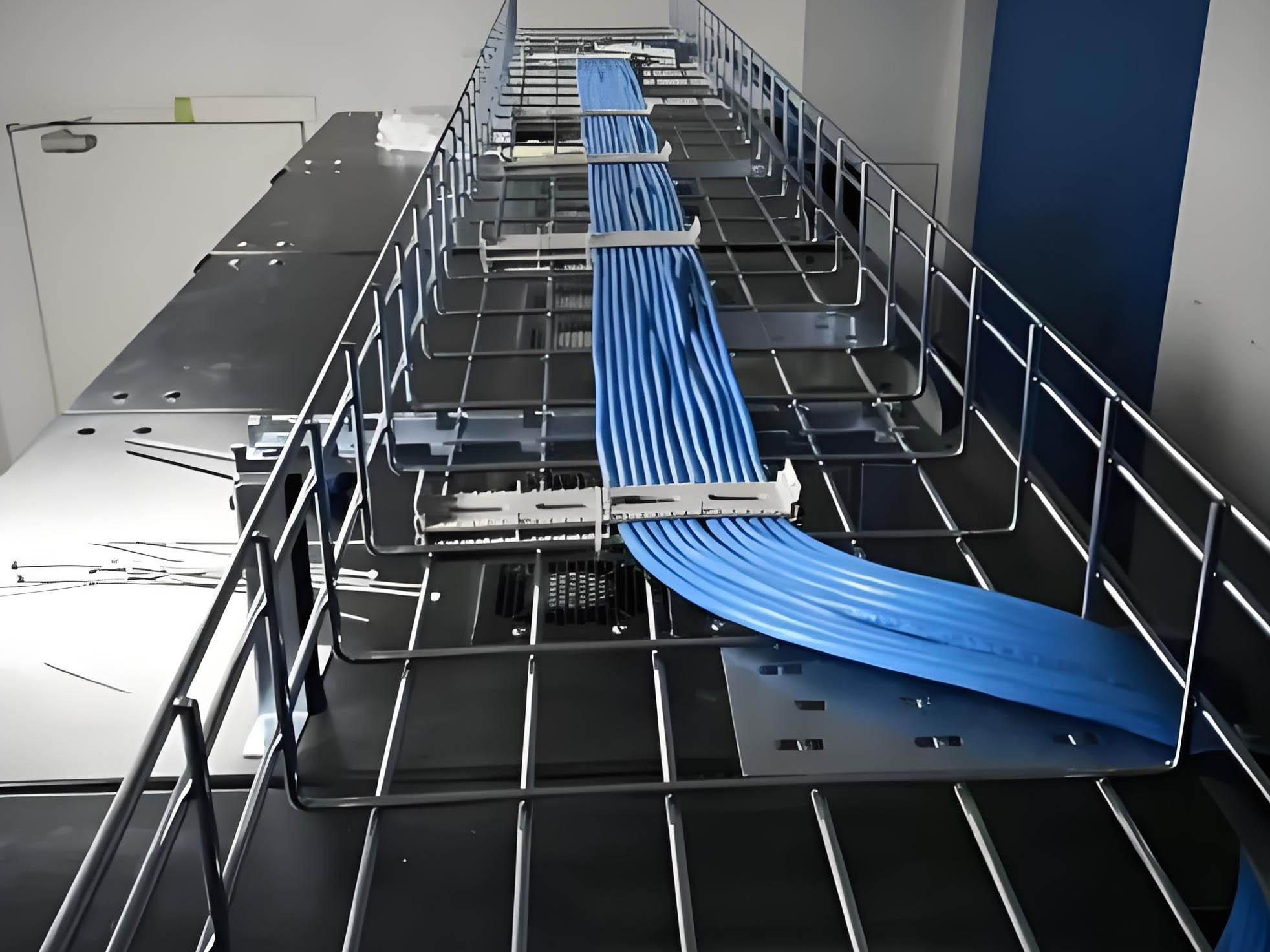
Clarify Project Drawings & On-Site Actual Conditions First
Before starting any material calculation, sorting out drawing information and verifying on-site conditions is the premise of accurate takeoff. Drawing data often has deviations from actual construction environments, and blind calculation will directly cause estimation errors.
Sort out wiring route and functional zoning
Carefully check electrical construction drawings, mark all cable tray laying routes, and distinguish indoor, outdoor, overhead and pipe corridor zoning. Different areas match different tray types and surface processes. For example, outdoor anti-corrosion trays and indoor ordinary trays cannot be mixed in estimation, which can effectively avoid material model mismatch.
Verify on-site obstacle and installation space
Recheck on-site beam height, column position, pipeline crossing and equipment occupation areas. These obstacles will increase the use of elbows, tees and reducing fittings. Only combining drawing data with actual site conditions can calculate the true quantity of special accessories and prevent missing materials.
Confirm project specification and safety standards
Confirm the tray specification standards required by the project, including tray width, height, material type and surface treatment process. Unified specification calibration at the initial stage can avoid mixed estimation of different specifications and ensure consistent material matching for the whole project.
Calculate Core Cable Tray Main Material Quantity
The main material calculation is the core part of cable tray takeoff, focusing on straight tray length statistics and reasonable segmentation layout, which determines the overall material consumption baseline of the project.
Count total straight tray laying length
Calculate the linear length of each wiring section one by one according to the drawing route, and sum up the total length of straight trays. It is necessary to distinguish ladder tray, solid bottom tray and perforated tray according to different power and weak current wiring areas, and count them in separate categories to avoid statistical confusion.
Reserve reasonable construction splicing allowance
In actual construction, tray splicing, cutting adjustment and on-site fine-tuning will produce material loss. It is necessary to add 3%–5% construction allowance on the basis of theoretical calculated length according to project scale and construction difficulty. Complex multi-turn routes can appropriately increase the allowance to prevent material shortage.
Classify statistics by specification and process
Classify and count trays of different widths, heights and surface treatments (spraying, galvanizing, stainless steel) separately. Independent statistical accounting of indoor and outdoor special trays can effectively avoid subsequent material receiving confusion and budget calculation errors.
Accurately Count Special Tray Fittings
Many estimators only count straight trays and ignore special fittings, which is the main cause of frequent material missing during construction. Special accessories adapt to route turning, branching and height change, and must be accurately counted one by one in takeoff work.
Count turning and connecting fittings
Mark and count all horizontal elbows, vertical up elbows and vertical down elbows according to the wiring route turning points. For multi-branch wiring positions, accurately count tees and cross fittings to ensure that all route transition parts have matching supporting accessories.
Calculate variable diameter and height adjustment accessories
For sections with changed cable quantity and tray specification switching, count reducing joints; for ceiling height difference and layered wiring positions, match height adjustment accessories. These small accessories are easy to miss, but directly affect the smooth progress of on-site installation.
Count cover plates and sealing accessories
Outdoor laying, dust workshop and closed wiring areas need matching tray cover plates. Calculate the total length of cover plates and supporting sealing strips according to the length of closed trays, and reserve a small amount of loss allowance.
Estimate Supporting Hardware & Installation Accessories
Supporting and fixing accessories are the foundation of stable tray installation. Scientific estimation of hanger spacing and accessory quantity can avoid insufficient fixing parts affecting construction progress and installation quality.
Calculate hanging brackets and supports
Determine the support spacing according to tray specification and installation standards (usually 1.5m–2m for conventional trays). Calculate the total number of hangers and bottom supports according to the total laying length, and increase the number of supports at turning points and heavy-load sections appropriately.
Count connecting bolts and fasteners
Each tray splicing point needs matching bolts, nuts and gaskets. Calculate the number of fasteners according to the number of splicing sections, and reserve 5%–10% spare parts loss to cope with on-site installation loss and damage.
Reserve auxiliary installation materials
Including expansion bolts, fixing pressing plates, insulating gaskets and grounding accessories. These auxiliary materials are small in size but essential for installation. Complete estimation can avoid temporary procurement delays on site.
Final Check & Budget Optimization Skills
After completing the preliminary material statistics, final inspection and optimization are required to eliminate estimation errors and realize cost control while ensuring construction compliance.
Cross-check drawing and on-site material list
Compare the counted material list with the construction drawings again to check for missing turning fittings, wrong specification statistics and missing zoning materials. Focus on checking special parts such as outdoor transition sections and equipment connecting sections.
Adjust allowance according to project difficulty
For simple straight-line wiring projects, appropriately reduce the material allowance to avoid waste; for complex workshops with multiple turns, multiple layers and many obstacles, moderately increase the loss allowance to ensure sufficient materials for construction.
Optimize material matching to control cost
On the premise of meeting safety standards, reasonably match tray models and accessories. Avoid over-specification configuration leading to cost waste, and also prevent low-specification materials failing to meet project acceptance standards.
If you lack experience in cable tray takeoff and material estimation, or need professional material list verification and budget optimization for your project, contact BDCABLETRAY. Our professional engineering team provides free project drawing review, accurate material takeoff service and customized matching schemes, helping you avoid material waste and construction delay risks.
FAQ
1. What is the standard material allowance for cable tray takeoff?
For conventional flat wiring projects, a 3% to 5% material allowance is sufficient. For complex industrial workshops with multiple turns, layered wiring and many on-site obstacles, it is recommended to reserve 5% to 8% loss allowance. Reasonable allowance can effectively solve on-site cutting errors and installation loss without causing excessive material waste.
2. What are the most easily missed accessories in cable tray estimation?
Vertical elbows, reducing joints, tray cover plates and grounding fasteners are the most easily missed parts in takeoff work. Most estimators only count straight trays and conventional horizontal fittings, ignoring special transition accessories and auxiliary fixing parts, which often leads to material shortage and construction shutdown on site.
3. How to avoid large errors in cable tray material takeoff?
The most effective way is to combine drawing statistics with on-site rechecking. Do not rely solely on paper drawings for calculation. It is necessary to verify on-site obstacle positions, wiring adjustment requirements and special zoning needs, classify statistics by specification and region, and conduct secondary cross-inspection after the first calculation to greatly reduce errors.
4. Do indoor and outdoor cable trays need separate takeoff statistics?
Yes, they must be counted separately. Indoor ordinary spraying trays and outdoor anti-corrosion galvanized/stainless steel trays have different materials, processes and matching accessories. Mixed statistics will lead to wrong material model selection, unable to meet outdoor weather resistance and anti-corrosion requirements, and affect project safety and acceptance.
5. Can standardized takeoff reduce project overall cost?
Absolutely. Accurate cable tray takeoff avoids excessive material procurement and on-site inventory waste, and eliminates additional costs caused by temporary supplementary orders and construction delays. Standardized material matching also avoids over-specification redundant configuration, effectively optimizing the overall project budget and improving engineering profit margin.