



Building electrical rooms are the core power distribution hubs for commercial buildings, residential complexes, office towers and public facilities. All power supply lines, weak current signal cables and control wiring converge and branch in this confined space. Unlike conventional corridor overhead wiring, electrical room cable laying features dense cable aggregation, high load concentration, frequent later maintenance and strict fire safety standards.
Unreasonable cable tray planning often leads to messy cable stacking, poor heat dissipation, difficult troubleshooting and even fire safety hazards. Many construction and electrical teams focus only on quick installation while ignoring standardized layout principles, resulting in unqualified project acceptance and high long-term maintenance costs. As a professional building cable tray solution provider, BDCABLETRAY summarizes practical, code-compliant and site-verified electrical room tray planning and layout tips in this guide, helping engineers complete standardized wiring design efficiently.
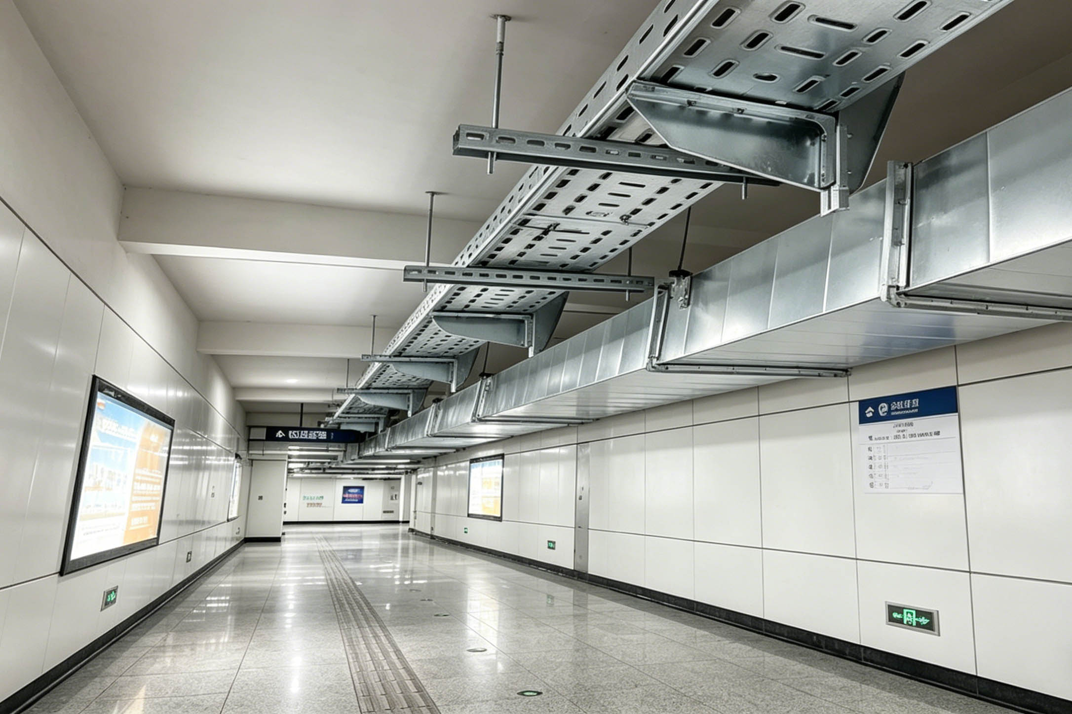
Understand Electrical Room Wiring Characteristics & Layout Principles
Before designing cable tray layouts, it is essential to clarify the unique operating environment and wiring rules of building electrical rooms. All layout designs must comply with national building electrical codes and international wiring standards, taking safety, stability, heat dissipation and maintainability as the core priorities.
Dense Cable Concentration & High Heat Generation
Electrical rooms gather a large number of main power cables, branch distribution lines and weak current signal wires. Long-term high-load operation generates continuous heat. Ordinary crowded laying without standardized tray grading will cause local heat accumulation, accelerate cable insulation aging, and affect the stable operation of power distribution equipment.
Strict Fire Safety & Isolation Requirements
As key fire control key areas of buildings, electrical rooms require strict layered isolation and fire blocking for cable trays. Power cables and weak current signal cables cannot be mixed randomly. Cross-regional laying must be equipped with fire blocking accessories to prevent flame spread along cables in case of fire accidents.
Prioritize Later Maintenance & Troubleshooting Space
Building electrical systems need regular inspection, cable replacement and circuit upgrading. Unreasonable tray occlusion and compact layout will block maintenance channels, increase the difficulty of fault investigation and daily overhaul, and easily cause secondary damage to cables and equipment during operation.
Unified Layout & Neat Standardization
Electrical room tray layout affects project acceptance and daily standardized management. Irregular bending, disordered height layering and inconsistent spacing will lead to unqualified engineering evaluation, failing to meet the standardized construction requirements of modern building electrical projects.
Scientific Cable Tray Type Selection for Electrical Rooms
Different cable types and laying positions in electrical rooms correspond to different tray styles. Reasonable type selection is the foundation of standardized layout. Blindly using a single tray model will cause poor heat dissipation, insufficient bearing capacity and non-compliant isolation.
Ladder Tray for Main High-Load Power Cables
For thick main power cables and high-current distribution lines in electrical rooms, ladder cable trays are the preferred choice. The hollow ladder structure provides excellent ventilation and heat dissipation, effectively solving heat accumulation of high-load cables. Its strong bearing capacity adapts to long-distance large-spec cable laying, avoiding deformation and sagging caused by heavy load.
Perforated Tray for Weak Current & Signal Cables
Network cables, monitoring lines, communication signal lines and building control cables are suitable for perforated cable trays. Uniform hole spacing ensures balanced heat dissipation and ventilation, while preventing small signal cables from slipping and falling. It maintains neat wiring and avoids signal interference caused by messy cable stacking.
Solid Bottom Tray for Fireproof & Isolation Zones
For cable laying close to distribution cabinets, fire partition boundaries and electrical room wall penetration positions, solid bottom cable trays are matched. The fully closed structure cooperates with fire blocking plates and sealing materials to form a complete fireproof isolation system, preventing flame and smoke from spreading along the tray gap.
Wire Mesh Tray for Light-Duty Auxiliary Wiring
For low-load auxiliary circuits, temporary control lines and frequently adjusted wiring areas in electrical rooms, lightweight wire mesh cable trays are more applicable. They feature flexible installation, clear wiring vision and convenient later adjustment, suitable for dynamic upgrading of building auxiliary electrical systems.
Core Standard Layout & Planning Tips for Electrical Rooms
Combined with on-site construction experience and building electrical specifications, BDCABLETRAY sorts out key layout details covering layering, spacing, trend planning and isolation protection, helping teams avoid common construction mistakes.
Strict Layered Laying for Power and Weak Current Cables
Strictly separate strong power cables and weak current signal cables in electrical rooms, and lay them in layers through different trays. Place high-current power cables on the upper layer and weak current signal cables on the lower layer, maintaining standardized vertical spacing. This layout effectively avoids electromagnetic interference, ensures stable signal transmission and safe power supply operation.
Standardize Tray Height & Horizontal Spacing
Reserve sufficient operation and heat dissipation space during tray installation. The vertical spacing between upper and lower trays strictly follows electrical specifications to avoid heat superposition. The horizontal distance between parallel trays reserves maintenance channels, ensuring staff can inspect, maintain and replace cables without obstacles.
Simplify Cable Trend & Reduce Cross Overlapping
Plan tray routes in a straight line as much as possible, reduce unnecessary bending, crossing and overlapping. Concentrate incoming and outgoing lines of distribution cabinets to avoid scattered wiring. Unified trend planning makes the cable circuit clear at a glance, greatly improving the efficiency of daily fault investigation and circuit sorting.
Standardized Fire Blocking & Wall-Penetrating Protection
All trays penetrating electrical room walls and floor gaps must be filled with fireproof sealing materials and equipped with special fire baffles. Segmented fire blocking is set for long-distance tray laying to form multiple fire isolation zones. This effectively prevents fire from spreading along cable passages and meets building fire protection acceptance standards.
Reserve Sufficient Expansion & Upgrading Space
Building electrical systems will be upgraded and expanded with functional iteration. Tray layout cannot fully fill the wiring space. Reserve spare trays and vacant laying positions according to 10%-20% of the total cable capacity, facilitating later circuit addition and equipment upgrading without overall reconstruction.
Reasonable Matching of Support & Fixing Accessories
Configure galvanized standardized brackets and anti-loosening bolt accessories for electrical room trays. Increase support density at bending points and cable concentrated load positions to prevent tray deformation and cable sagging. Ensure the overall laying is flat, neat and stable, adapting to long-term uninterrupted operation of building electrical systems.
Common Layout Mistakes to Avoid in Electrical Room
Most electrical room wiring hidden dangers come from non-standard detail layout. Avoiding the following common mistakes can effectively improve project quality and pass acceptance smoothly.
Mixed Laying of Strong and Weak Current Cables
Random mixing of power cables and signal cables will cause serious electromagnetic interference, resulting in unstable building signal system and even equipment failure. Layered tray isolation must be adopted to ensure independent operation of different circuits.
Excessive Cable Density & Insufficient Heat Dissipation
Blindly pursuing high-density wiring leads to full-load cable stacking, poor air circulation and serious heat accumulation. Long-term operation will accelerate insulation aging and induce leakage and short-circuit faults. Always control cable laying density within the standard range.
Ignoring Fire Blocking & Gap Sealing
Many projects ignore wall-penetrating gap sealing and segmented fire blocking, resulting in unqualified fire protection. Once a fire occurs, flames will spread rapidly along cables, expanding the scope of accidents and bringing huge safety losses to the building.
No Reserved Maintenance & Expansion Space
Compact layout without reserved gaps leads to difficult later maintenance and no space for circuit upgrading. It will cause repeated renovation and waste of engineering costs in the later stage of building operation.

BDCABLETRAY Electrical Room Tray Layout Advantages
Code-Compliant Standardized Design
All BDCABLETRAY cable trays are designed and produced in strict accordance with building electrical specifications, matching electrical room layered wiring, fire protection isolation and heat dissipation requirements, ensuring one-time pass of project acceptance.
Multi-Type Matching for Differentiated Wiring
Complete product lines including ladder, perforated, solid and mesh trays meet the differentiated laying needs of power cables, weak current cables and auxiliary circuits, realizing scientific classified wiring.
Durable Anti-Corrosion & Stable Performance
Galvanized and powder-coated surface treatments adapt to long-term indoor electrical room operation environments, resisting moisture and dust erosion, ensuring long-term stable operation of the tray system and reducing maintenance frequency.
Customized Layout & Flexible Adaptation
Support personalized tray size, bending and accessory customization according to electrical room space structure and wiring volume, solving the layout difficulties of irregular spaces.
If you need standardized, code-compliant cable tray planning and layout solutions for building electrical room projects, contact BDCABLETRAY. We provide free electrical room wiring scheme design, professional type selection guidance and factory direct supply services to help you complete safe, neat and long-term stable electrical wiring construction.
FAQ
1. Which type of cable tray is most suitable for building electrical rooms?
It depends on the cable type. Ladder trays are ideal for heavy-load main power cables for better heat dissipation and bearing capacity. Perforated trays fit weak current signal cables to prevent sliding and ensure stable heat dissipation. Solid bottom trays are used for fire isolation and wall-penetrating positions. Reasonable collocation of multiple tray types is the most scientific solution for electrical room wiring.
2. Why must strong and weak current cables be laid in separate trays in electrical rooms?
High-current power cables will generate electromagnetic fields during operation. Mixed laying with weak current signal cables will cause serious signal interference, leading to unstable network, monitoring and control systems. Layered and separated tray laying effectively isolates electromagnetic interference and ensures the safe and stable operation of building electrical systems.
3. What are the key fire protection requirements for electrical room cable tray layout?
All wall and floor penetration gaps of trays must be tightly sealed with fireproof materials. Long-distance horizontal laying needs segmented fire blocking measures. Fire-resistant trays can be matched for key fire prevention areas. Standardized fire blocking can effectively prevent flame spread along cable passages and meet building fire acceptance standards.
4. How to reserve reasonable upgrading space for electrical room tray layout?
During the initial design, reserve 10%-20% spare wiring capacity and vacant tray positions according to the total cable quantity. Avoid full-load laying. Prioritize universal modular trays and standard accessories to facilitate later cable addition, circuit adjustment and equipment upgrading without overall reconstruction.
5. Can BDCABLETRAY provide one-stop layout design for electrical room cable trays?
Yes. BDCABLETRAY’s professional engineering team provides full-process services including on-site space survey, cable type sorting, tray type selection, layered layout planning and fire protection scheme design. We customize compliant and practical layout solutions for different building electrical room scales and wiring demands to ensure construction standardization.